by Brian Coombs
The wheel is a very complicated component. It has to cope with very high loads applied to it, and has many other constraints imposed on its design.
When we started our design work, we did not know where we were going to be running, or even what the surface would be – salt as on Lake Eyre in Australia or playa as at Black Rock in USA. Our design was therefore based on the data we had from Thrust SSC and started with a wheel that was 900mm in diameter and 150mm wide, which we thought would have to be made of titanium.
One of the first things we did was to set out the suspension geometry points that we thought would give us the correct handling characteristics. We settled on the following:-
- 8 degrees king pin inclination
- 6 degrees castor
- 100mm Trail
- 2mm Offset.
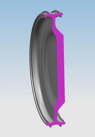 The position of the suspension points required us to have an asymmetric, or dished wheel (pictured left), which we thought would not be a problem. When we analysed the wheel and at 10300rpm (1050mph) though, the stresses within the wheel were exceedingly high.
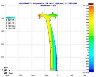
In the Asymmetric Wheel Stress Plot pictured right, the yellow and red colours indicate unacceptable levels of stress in the wheel.
 We spent a lot of time trying to reduce the stresses within a asymmetric titanium wheel with little success. It became clear that we would have to try something else.
One option was to come up with a suspension solution that would allow us to use a symmetrical wheel. This reduced the stress so much, that it looked like with a bit more improvement we could manufacture the wheel in aluminium - this was well worth follwing up for the savings in complexity of manufacture ... as well as a lot of hard-earned money!
The solution was a virtual steering axes suspension geometry, which allowed us to keep the suspension geometry we require with a symmetrical wheel. The downside to this is the reduction in suspension stiffness. With careful design, this can be minimised to an acceptable level.
Once we had decided on a symmetrical wheel, we used a parametric study to try and optimise the wheel shape. However, at this stage we still had no desert data so the wheel width was unknown. We would like to keep the wheel width to a minimum to reduce drag and weight, but it has to be wide enough to support the weight of the car without sinking into the desert too much. Although this parametric study gave us some good information on the what the final design should be, we needed the desert data.
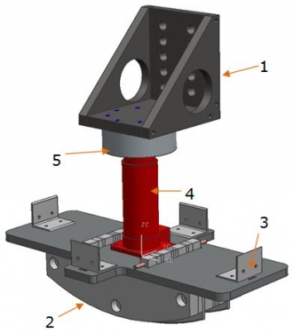 When Andy Green discovered Hakskeen Pan, he reported that the surface was consistently hard ... but just how hard was it? We manufactured a simple rig (picture right) that measured the load required to press a wheel segment into the desert and John Piper took it to Hakskeen Pan to test various areas (see Breaking Ground on Breaking Ground). From the results, we were able to get a much better idea of the wheel width required. Hakskeen is indeed very hard and I think we can reduce the width down to 120mm or maybe even a bit narrower, making an aluminium wheel viable.
What next?
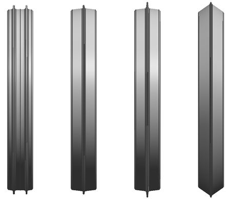
One of the last pieces in the design process is to look at the lateral forces that the wheel can generate. We have come up with 4 different wheel designs (see picture at the top of this page) which we will take to Hakskeen Pan and attach them to a steer force trailer in order to measure their ability to apply a lateral load. If this load is too high, the vehicle will have a tendency to roll over, if the load is too small, BLOODHOUND SSC will slide and be very difficult to control - it's a bit like a road car on ice. We will then have enough information to come up with a design which allows good control.