Based on an original article by Professor David Crolla
The key issue in the dynamic behaviour of BLOODHOUND SSC is maintaining its directional stability over its entire operating speed range from 0 to 1,000mph. The Car must also be able to steer and turn like a conventional wheeled vehicle, but its prime objective is to travel at extremely high speed in a straight line, rather than cornering, as is the case with Formula 1 racing cars, for example.
What is directional stability?
The term ‘stability’ is used in many vehicle design contexts, but it is important to define ‘directional stability’ clearly.
When a vehicle is perturbed from its equilibrium condition – for example straight running – it is directionally stable if the force and moment system causes it automatically to return to its original equilibrium condition.
Despite the enormous design challenges with this type of vehicle, there are only two fundamental sources of external forces and moments which contribute to its directional stability:
- interactions between the wheels and the ground
- aerodynamic properties.
Wheels vs the ground
We assume that BLOODHOUND's wheels can generate lateral forces in response to slip angles in rather the same way as we know tyres behave. The mechanics in this case are, however, completely different.
Tyres generate forces at the contact region due to friction between the rubber tread and the ground surface, but when solid wheels run on a deformable medium – for example some type of salt or silt desert surface – the force generation mechanism is controlled by the friction between the wheels and the soil, and the internal soil friction when it deforms. Hence two of the most serious shortcomings in attempting to predict the dynamic behaviour of BLOODHOUND are the lack of data and the lack of understanding of this wheel/soil interaction.
Aerodynamics and stability
There are three mechanisms by which the aerodynamic forces and moments have major influences on stability.
The first mechanism is in directly influencing the directional stability through the substantial aerodynamic side forces and yaw moments on the vehicle body: these forces and moments arise when the vehicle body acts at a small angle of attack relative to the straight ahead position. The net resulting aerodynamic side force and yaw moment are sometimes combined and referred to as a single force acting at the aerodynamic centre of pressure in side view.
Directional stability is associated with this centre of pressure being aft of the vehicle mass centre (or 'centre of gravity'). The extent to which the centre of pressure is aft of the centre of gravity is often referred to as the 'aerodynamic static margin'.
The second mechanism is associated with the wheels. For the non-steered wheels which may be directly in the airstream or housed within fairings, their aerodynamics simply add on to the body terms and are therefore included directly. However, steered wheels are capable of generating additional lateral forces by operating at an angle to the vehicle body and hence a different angle of attack relative to the airstream. They behave in a similar way to the wheel/ground system in generating a lateral force in response to a slip angle. The effectiveness of this mechanism depends very much on how much the steered wheels are in the airstream rather than hidden in the body.
The third mechanism is an indirect route. As the speed varies the aerodynamic downforce and pitch moment vary, and these in turn control the wheel loads, which in turn then influence their ability to generate lateral forces at the wheel ground contact region. On the Car it is proposed to manage these wheel loads throughout an entire run using programmable winglets over the front and rear axles.
Stable from 0mph to 1,000mph
The Car – rather obviously – has an enormous speed range. Rather than focussing attention on its extremely high speed range, however unique that may be, we have to remember that it must retain controllable (and preferably stable) behaviour right throughout the whole speed range.
Broadly speaking, it is fair to assume that its low speed behaviour (up to 200mph) will be dominated by the wheel forces, whereas at higher speeds it will be dominated by the aerodynamic behaviour, with some contributions from the wheel forces.
We therefore needed data or estimates of how the following parameters would change both with speed and acceleration/deceleration throughout the speed range in order to estimate a complete stability profile for the vehicle
- vehicle mass
- mass centre position
- aerodynamic forces and moments
- wheel loads
- wheel/soil interaction
One particular challenge will be to ensure that the steering system maintains an acceptable level of control and consistency over the vehicle trim throughout the speed range.
Calculating directional stability
The directional stability of the Car was analysed using a linear dynamics model using the MATLAB/Simulink package (see figure 1).
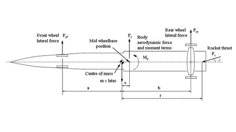 Figure 1: Plan view of vehicle model showing the wheel/ground and aerodynamic restoring forces and moments
The data requirements for this model posed some problems, however.
The vehicle layout, mass and inertia properties were relatively straightforward outputs from the overall CAD model. The aerodynamic force and moment data were estimated from the computational fluid dynamics prediction work.
However, estimating data for the properties of the wheel/ground forces proved to be one of the least certain areas. There was very little data in the off-road literature on the force properties of rigid wheels on deformable surfaces, and none at all above low speeds (several miles per hour), so we were forced to estimate these properties based on collecting together off-road experiences from a range of sources including Thrust SSC and Dieselmax.
The outputs from these modelling results were used in two ways:
- to predict the directional stability of the vehicle, and hence propose requirements for managing the airflow to achieve acceptable stability
- to understand the sensitivity of the predictions to assumptions in difficult areas, e.g. the wheel/ground contact forces.
Some of the design guidelines emerging from this study were that the designers should:
- maintain the vehicle mass centre ahead of the mid-wheelbase position
- maintain the aerodynamic centre of pressure aft of the mass centre
- maintain the axle loadings close to their static values with a bias towards slightly more at the rear.
All of these design guidelines related to vehicle directional stability were used by the design engineers when making decisions throughout the design process. They have informed key design decisions, such as the internal Car layout (to achieve, for example, the desired mass centre slightly ahead of the mid-wheelbase) and the sizing of the rear fin (to keep the centre of pressure aft of the mass centre).