There's been some new buzz words and acronyms in the Engineering Team recently, all lumped under the headings:
DoE and Parametric Study
DoE stands for Design of Experiments, but what does all that mean?
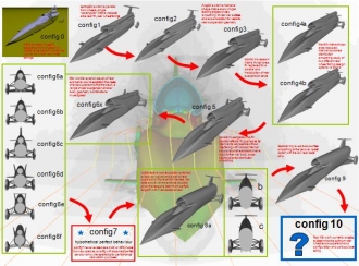 Since the design started back in 2008, there have been a number of "configurations" of BLOODHOUND SSC - see Configuration Development for a summary of configurations 1 to 10. Ben Evans produced a one page diagram that you may have seen if you have been to one of the team's presentations recently. This diagram (reproduced right) charts the progress of the shape of the car from first concepts, through the design changes (such as "Jet over Rocket" configuration) through to the current basic shape being produced at Configuration 10. Take a closer look here.
However, this isn't EXACTLY the final shape, as there are lots of tweaks still to be done to try and get rid of the unwanted lift on the tail as the speed increases and the shock waves have a less than desirable effect.
Sponsor Intel came on board to help with the CFD analysis, and the vastly increased computing power available to Ben Evans meant that more adjustments to the body shape could be considered. The problem was though, how do we go about it. It's not as easy as someone scratching their head and suggesting yet another variation!
Step 1: Parametric Study
The first stage of Parametric Study was to analyse the results of the aerodynamics so far, with the objective of determining which variations of the design caused the most effect - good or bad - on the aerodynamics.
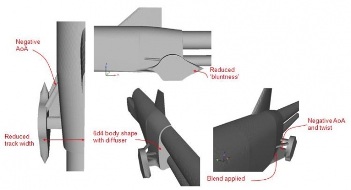
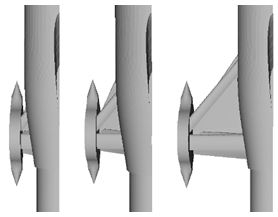 For instance, what effect does varying the wheel track have? See the diagram on the left - should the car have a narrow wheel track, or a wide one, or somewhere in between? Bear in mind we are looking at the aerodynamics only here, the effect on stability of the car is another story which will be covered later.
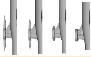 Or what about the wheel fairings? should the points be long and thin? or should they be stubby? or maybe pointy at the front and blunt at the rear? see these variations in the diagram on the right.
So what are all the different parameters that went into this study? They included the following ...
- delta leading edge sweep angle
- base area
- rear wheel track
- fairing spike length
- fairing spike height
- boat-tail angle
- body-delta angle
- ride height
- delta angle of attack
- delta strut camber
- ‘spam’ shape
- diffuser
- suspension ‘blister’
- delta leading edge ‘crank’
- delta – body blend
- fairing radius
- fairing cone diameter
- delta AoA
Of course, varying any one of these will have an immediate effect on some (or all!) the others. So many, many calculations were done stepping through different values of these parameters, and the list was narrowed down to a few that had the most effect. These turned out to be ...
Step 2: Design of Experiments
This step of the process is here ... find out what happens next!
The Engineering Team involved in this study are: Mark Chapman, Ben Evans, Bjorn Rodde and Iain Niven.