by Hywel Vaughan
At the end of my last article, we had finished with a concept for a steering wheel. A mixture of sketches and blue foam models, we had decided on how the wheel would be laid out. We had seen what had been done on Thrust SSC, which route JCB Dieselmax had taken, and now it was time for us to develop our own, unique steering set up.
Before we get as far as a moulded steering wheel though, we need to develop a rig. There are lots of questions to ask when constructing the interface for a supersonic vehicle; and all of them need a definitive answer. What is it we need to know though? Is it not just a wheel that attaches to a shaft?
With the exception of the shape of the grips themselves, we need to know how wide we will space them. We need to know where we will have switches, where we will have triggers, and of course the obvious one - how many do we need. We need to know what angle the wheel will be at, and what angle the grips will be at on the wheel (be assured, they are not the same thing!).
So, we need to construct a rig. Something that can gather all of this data in one sitting (Andy Green is a very busy man!) and can be retained for reference afterwards. Bring on the designer's forever faithful friend - MDF.
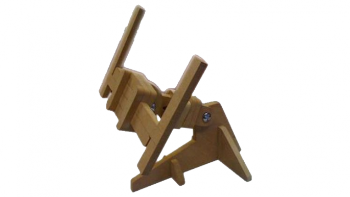
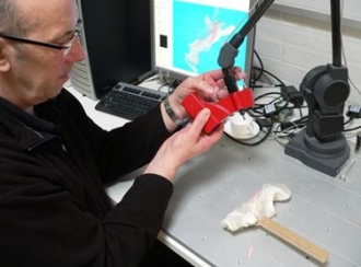
The rig (pictured above), although being small and slightly - how do I say it - blocky - may be simple, but when used and marked it provides all of the data needed to construct a steering wheel. It is fully adjustable, pivots in all axis and is a cost effective and accurate way of doing what we need.
 Next comes the fun bit. Moulding it to Andy's hands. We coat the grips with clay and get Mr 1000mph to sit down and shape it to something he feels comfortable with.
Now you may think that this is not a particularly high tech method of working. Surely the team designing the world's fastest car would use something more fancy than modelling clay and some MDF? Something with lasers perhaps? Well the truth is we do, but we will come to that. First though I must tell you that this is not as antiquated a method as you may think.
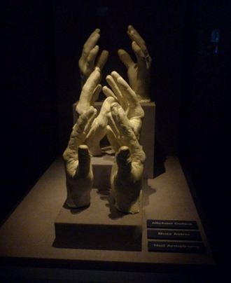
A few weeks after I had got Andy's hands to mould the steering grips, I had the pleasure of visiting Kennedy Space Centre in Orlando, Florida. What did I see on display there? Clay moulds in the shaped of Neil Armstrong, Buzz Aldrin and Michael Collins' hands. It is a simple and effective way of understanding the ergonomics of a person. Granted at NASA they had moulded the hands rather than the handles, but the principle is the same. In primary school you draw around your hands to understand the size - we just do the same in three dimensions.
If it works for the first man on the moon, then the likelihood is it will work for the fastest man on earth (and we all know what these men talk about - see Andy's diary).
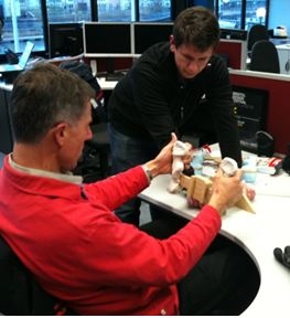
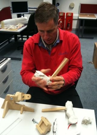 After a meeting with Andy, we set up the rig. One and a half packs of air drying clay were layered on the MDF spine, Wing Commander Green positioned at a desk in a similar position to that of the car, and thick racing gloves applied to give a more accurate representation of Andy's hands in the vehicle. Then we moulded the grips. We shaped each grip around his hands, marking on the positions of buttons and triggers, pinches and grasps. And that was it. Once completed, we left the clay to dry.
So we ended up with a clay moulding of some steering wheel grips. What happens next? As simple as it would be to drill some holes in the clay and attach the switches, I have my doubts as to whether clay can handle the stern grip of Andy Green travelling at Mach 1.4. What we need to do is create a CAD model of the steering wheel. This can then be altered, stress tested and eventually manufactured out of something a little bit more sturdy.
 But now comes the difficult task - converting a model from the physical to the electronic. It could be done manually. It would take quite a while, but it could be done. There is however a much more efficient and accurate way of getting the data.
Men with lasers.
David Huson and Peter Walters from the Centre of Fine Print at UWE are masters in their field. Experts in the application of digital technology in art, they were just the people we needed. A friendly phone call to them and a quick explanation of what we were after and they clearly understood the problem and offered their services (UWE being a founder sponsor of the project has been invaluable). A short walk later and I found myself in an office crammed full of electronic equipment that I expect I shall never fully understand.
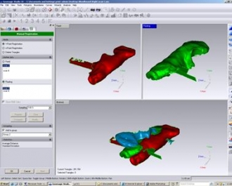
 Using lasers, David scanned the profile of each of the grips. This was meshed with other scans to create a three dimensional model of each handhold. Wonderful! No long hours carefully measuring each cross section of the clay model. No problems trying to get the level of accuracy right. One process, one highly accurate CAD model.
At this point you may think that the job is done. We have a CAD model, we know how far apart the grips will go, at what angle they will sit and where the buttons will be. Well, not quite. In fact, we haven't even begun the hard part yet. Now we need to change this electronic copy of some clay moulded to Andy Green's hands into a working model...
 ...But that is another story.